A Voltage Divider circuit is a simple but very useful circuit in electronics and it is applied and vital to many electronic circuits. Looking at the schematic drawing below you can see that the circuit contains 2 resistors in a series. The Voltage inbetween the 2 resistors R1 And R2 is the voltage we are interested in.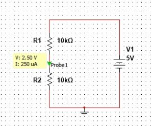
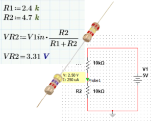
Looking at the calculations now you can see that the voltage VR2 is obtained by the simple formula as shown below.
Some of the applications of voltage dividers can be seen below.
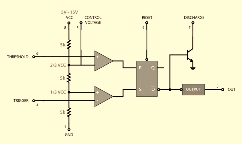
As can be seen below the 3 series resistor set the voltage for the 2 comparators for the functioning of the 555 timer.
for example if the VCC is 12V then the top comparator gets 2/3 of 12V which is 8V and the bottom comparator gets 4V.

This way the voltage divider is used in many electronic circuits to divide voltage for specific needs.
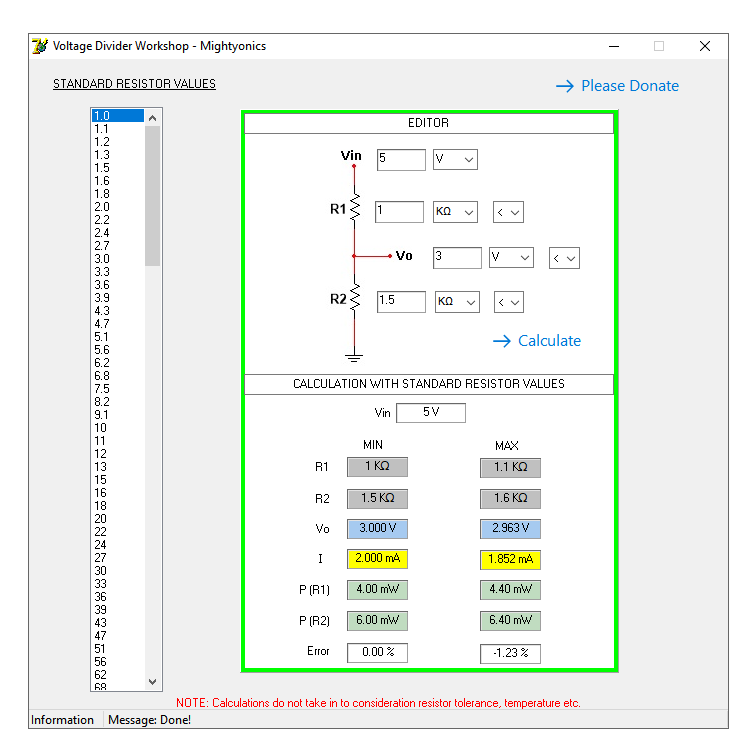
You can download a voltage divider calculator app for windows – vdw(VoltageDividerWorkshop)